What the system must achieve
convert long linear motion into a controller-ready position value
Draw-wire sensor application
Measure hydraulic-cylinder extension without modifying the cylinder rod or internal seal package.
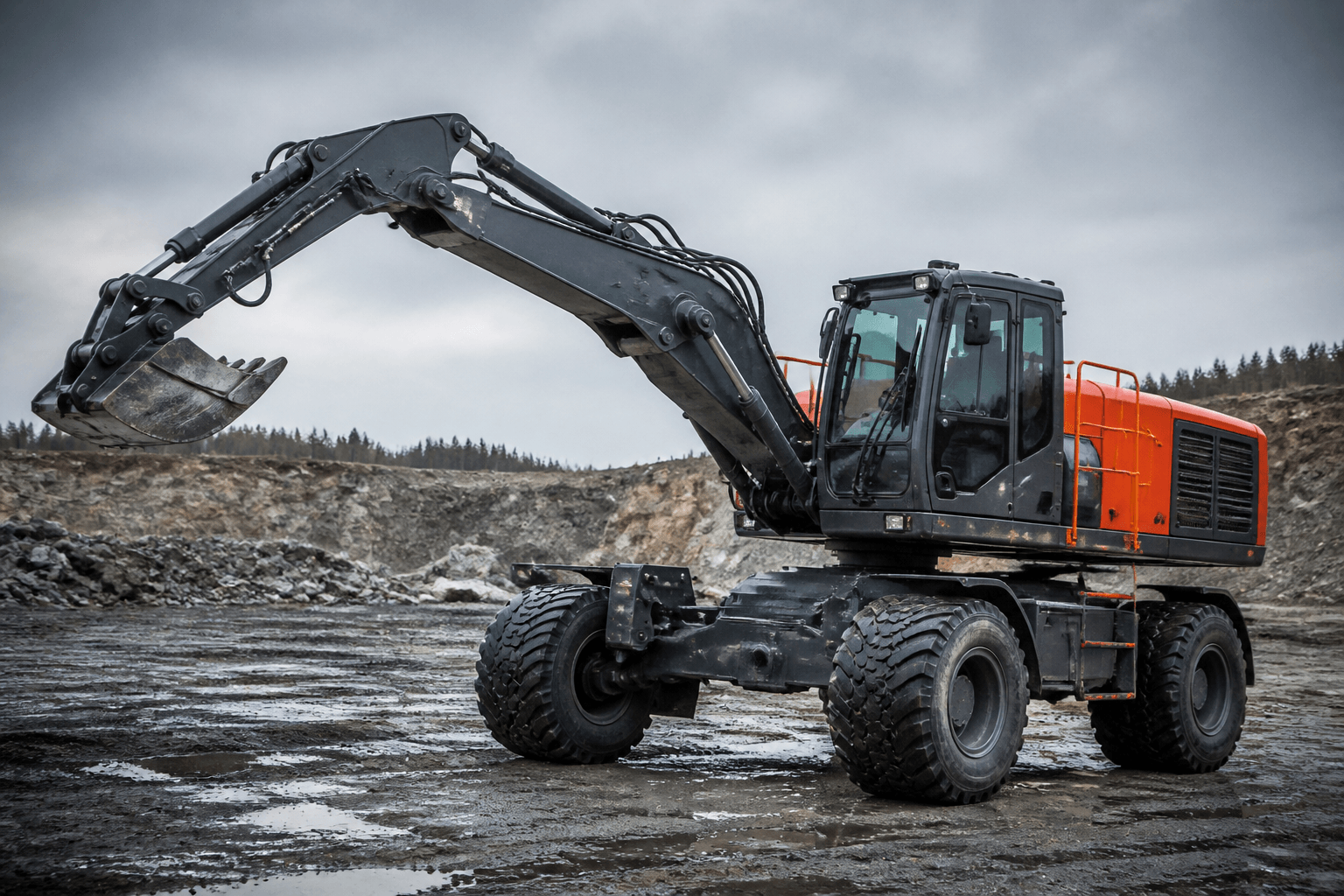
01 · THE MACHINE
A draw-wire displacement sensor measures hydraulic cylinder extension and retraction by extending a spring-retracted stainless-steel cable from a fixed sensor body to the moving point. The correct configuration combines measuring range, 10- or 12-bit absolute resolution (or 1,000/2,000 PPR incremental output), controller interface and IP54, IP68 or project-confirmed Ex protection.
02 · WHAT TO MEASURE
keep the measuring cable aligned, guarded and outside the load path
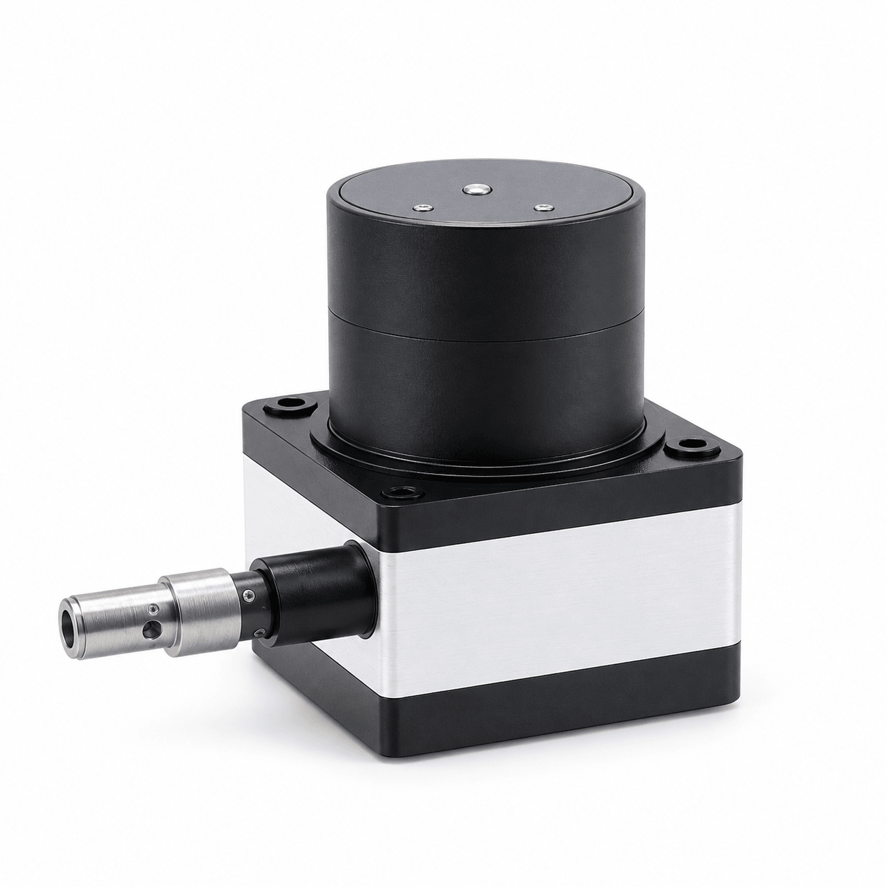 VIEW PRODUCT PAGE →
03 · RECOMMENDED PRODUCT
The selected travel determines the mechanical family, housing dimensions, winding wheel and pull force. The controller interface and environmental protection are then matched to the installation.
04 · HOW IT WORKS
The draw-wire sensor converts a moving point into a continuous linear position value.
A spring-retracted measuring cable follows the moving mechanism. The internal encoder converts cable-drum rotation into an absolute digital, analog or incremental signal for the machine controller.
convert long linear motion into a controller-ready position value
Measure the full working travel and add appropriate setup and overtravel margin. Choose 10/12-bit absolute feedback or 1,000/2,000 PPR incremental feedback. Match RS485, CANopen, SSI, BiSS-C, analog or pulse output to the controller. Approve the range-specific housing and drawing; keep the measuring cable aligned, guarded and outside the load path.
05 · EXPECTED RESULT
SELECTION TABLE
Use this table as an initial engineering checklist. Final model configuration must be confirmed against the controller, mechanical drawing and operating environment.
ENGINEERING PROCESS
Measure the full working travel and add appropriate setup and overtravel margin.
Choose 10/12-bit absolute feedback or 1,000/2,000 PPR incremental feedback.
Match RS485, CANopen, SSI, BiSS-C, analog or pulse output to the controller.
Approve the range-specific housing and drawing; keep the measuring cable aligned, guarded and outside the load path.
RELEVANT PRODUCTS
Protected linear-position measurement for outdoor, washdown and water-infrastructure applications.
View parameters and drawings →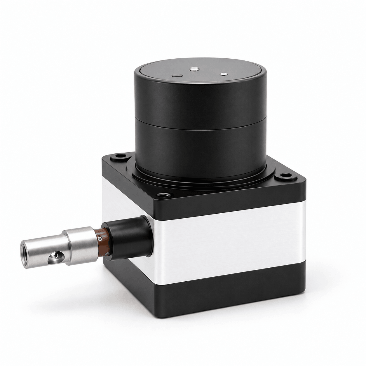
Absolute linear position and speed feedback with power-off memory for short, medium and long travel.
View parameters and drawings →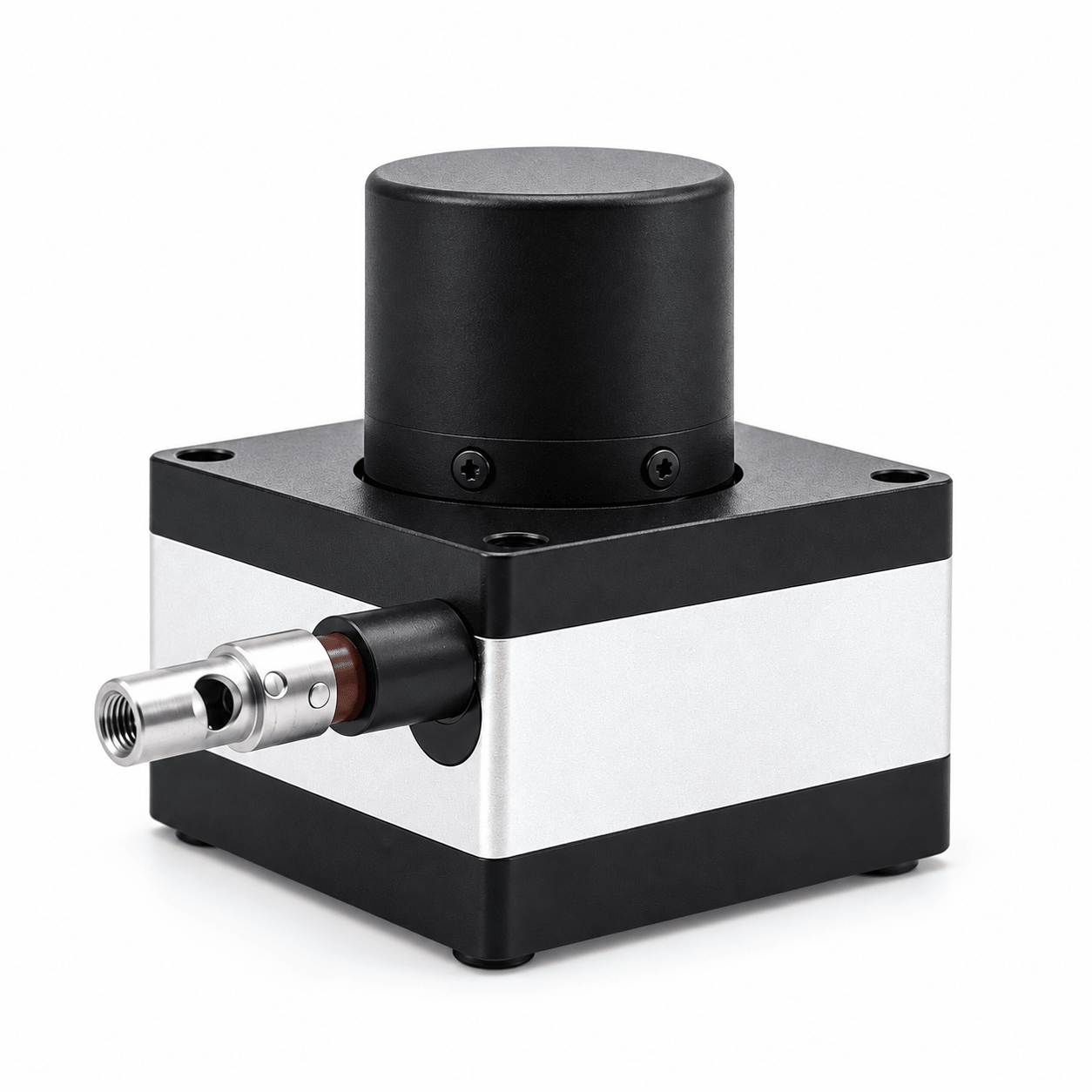
Direct analog linear-position feedback for standard PLC current and voltage inputs.
View parameters and drawings →COMMON QUESTIONS
No. It is a measurement element only and must never be used as a load-bearing or safety-support cable.
The selected travel determines the BRT27 or BRT38 mechanical family, housing dimensions, winding-wheel diameter and nominal pull force.
No. Confirm the complete assembly, cable exit, corrosion exposure, mounting orientation and the supplier's stated water test condition.
RELATED GUIDANCE
EDITORIAL SCOPE
FOSAI consolidates available supplier technical material into a buyer-oriented selection guide. Parameters, certifications and compatibility are not generalized across every model; the final suffix, controlled drawing and project conditions must be confirmed before ordering.
MODEL SELECTION SUPPORT
Include the existing model, controller interface, supply, measurement range, shaft or mounting drawing, environment and quantity.
Request technical selection →