Screened intake
Water enters through the perforated band and passes through the hydraulic stages.
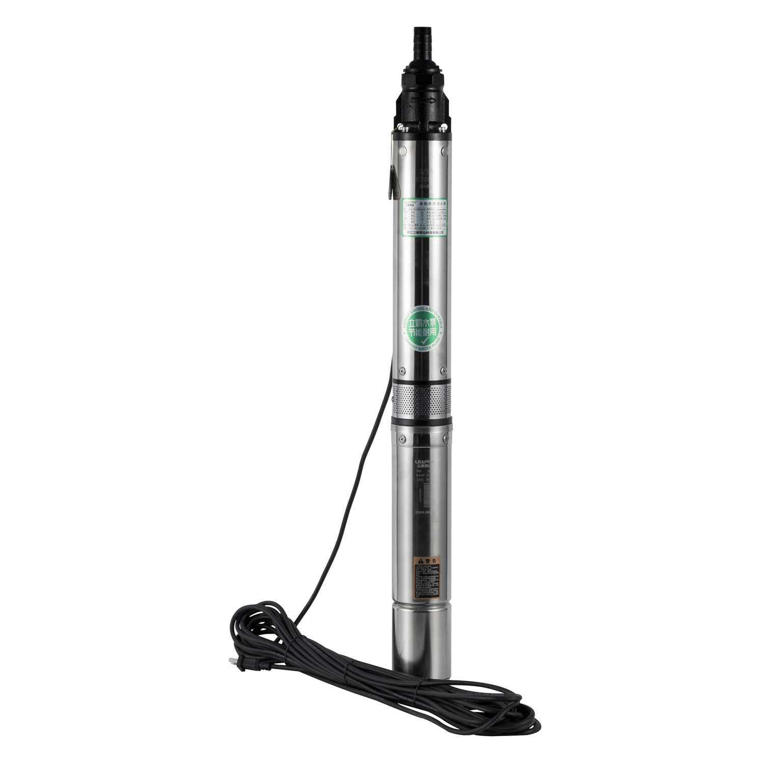
Y80QJD + Y90QJD · OIL-FILLED
QJD pumps pair a slim multistage hydraulic section with an oil-filled motor. Y80 covers 2 and 3 m³/h rated-flow families; Y90 extends the choice from 2 to 15 m³/h. Select by the actual flow, total head and well clearance.
PRODUCT INFORMATION
The right series is determined by the well and operating point—not motor power alone.
Water enters through the perforated band and passes through the hydraulic stages.
Impeller and diffuser stages raise pressure. Use the Q–H curve to check the head available at required flow.
The submerged cylindrical motor drives the stage stack. Confirm voltage, cable and protection for the ordered model.
Check the pump's actual outside diameter against the well casing, including the cable and installation tolerance.
APPLICATION FIT
Dynamic water level, pipe losses and required outlet pressure define the total head. Well diameter determines which pump can be installed safely.
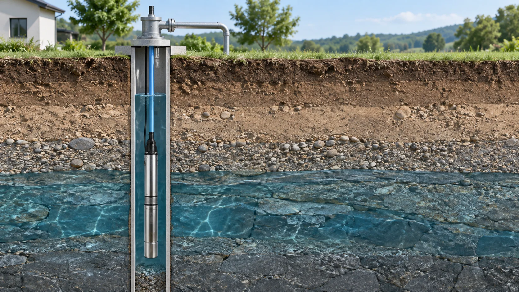
Use the required outlet flow and drawdown level to calculate the duty point.
Match the operating flow to the irrigation zone and its pressure losses.
Confirm the daily demand and storage or trough-filling schedule.
Include lift, delivery-pipe friction and outlet pressure in total head.
MODEL SELECTION
Choose the flow family first. Then compare model head, connection and power, with Q–H data and construction below.
Compact 220 V oil-filled multistage borehole pumps with 2 and 3 m³/h rated-flow families for small-well water supply.
| Model | Rated flow | Rated head | Maximum head | Power | Outlet |
|---|---|---|---|---|---|
| Y80QJD2-40/10-0.6 | 2 m³/h | 40 m | 53 m | 0.6 kW | 1" |
| Y80QJD2-48/12-0.8 | 2 m³/h | 48 m | 63 m | 0.8 kW | 1" |
| Y80QJD2-56/14-0.9 | 2 m³/h | 56 m | 74 m | 0.9 kW | 1" |
| Y80QJD3-38/10-0.6 | 3 m³/h | 38 m | 43 m | 0.6 kW | 1" |
| Y80QJD3-46/12-0.8 | 3 m³/h | 46 m | 52 m | 0.8 kW | 1" |
| Y80QJD3-54/14-0.9 | 3 m³/h | 54 m | 60 m | 0.9 kW | 1" |
Check the ordered model's dimensions and electrical data before installation. For Y80, one catalog shows Ø88 mm while a later model list shows Ø92 mm; confirm the actual outside diameter against the well casing.
Every circular marker reproduces a value from the supplied Y80QJD technical table. The connecting line uses shape-preserving interpolation and does not create additional measurements.
| Flow Q | 0 m³/h | 1 m³/h | 1.5 m³/h | 2 m³/h | 3 m³/h | 4 m³/h |
|---|---|---|---|---|---|---|
| Head H | 74 m | 70 m | 66 m | 56 m | 40 m | 15 m |
Switch views, then select a structural group to understand its role. The exact number of stages and service components depends on the ordered model.
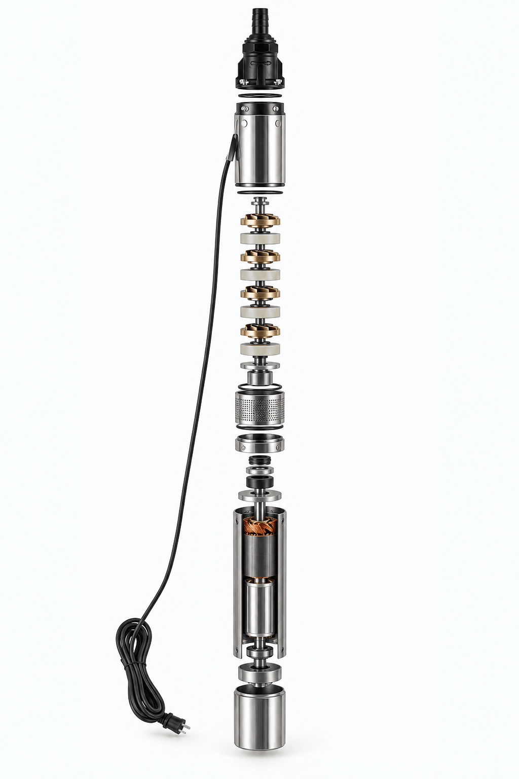
Repeated stages add head; the stage count changes with the selected model.
The expanded image is a new visual reconstruction, not original-factory CAD or a verified spare-parts drawing. Do not use its visual details as orderable part numbers.
COMMON QUESTIONS
Provide bore diameter, static and dynamic levels, required flow and pressure, pipe details and power supply.
No. Selection should use the pump curve at the required operating flow and calculated total dynamic head.
REQUEST SELECTION
Include well casing diameter, dynamic water level and power supply.